Taking the same picutre at a finite distance introduces various distortions, the most serious of which (the "fisheye" effect) causes horizontal and vertical lines to be curved. This can be corrected by calibrating the disparity, using an image of a flat page on which horizontal and vertical lines are drawn. We define the horizontal and vertical disparity fields, as the components of a two-dimensional vector field that can be used to transform the camera image to the image that would be acquired from a camera at infinity. In that image, the lines would again be straight and perpendicular.
A further complication occurs when the page bends (without stretching or folding) out of the plane perpendicular to the OA. Call the OA the "z-axis". Then the bending of the page can be described by a scalar field Z(x,y), which is the position of the paper above or below a plane perpendicular to the OA. Let the origin (x = 0, y = 0) be the point where the OA intersects the page. Consider a page with thin horizontal lines. For a camera at "infinity", these lines continue to appear straight if Z(x,y) is independent of y (e.g., bending around vertical lines), But if the camera is at a finite distance they will bend symmetrically about a vertical line (x = 0) that goes through the OA. For the general case with a camera at finite distance and Z depending on both x and y, a perfect dewarping of the image based on only horizontal lines in the page is not possible. But we can do fairly well with a very simple approach, described in the next section.
Then to get a smooth vertical disparity function V(x,y), we fit each line to a parametric curve. In most cases a quadratic will suffice; higher order fits tend to amplify outliers and printing defects. After the quadratic fit, the result is sampled at equally spaced intervals in x. Then for each value of x for which we have sampled disparities at several values of y, fit another quadratic, and sample that at equally spaced intervals in y. The result is a smoothed V(x,y) at equally spaced intervals in both x and y. Now interpolate, equivalent to up-scaling, to get the disparity values at all points (x,y). After mapping, all the lines should be horizontal.
What about the horizontal disparity? We used a very simple model for H(x,y) == H(x), independent of y and based on the difference in vertical disparity at the top and bottom. See the description in the code header in dewarp.c for details.
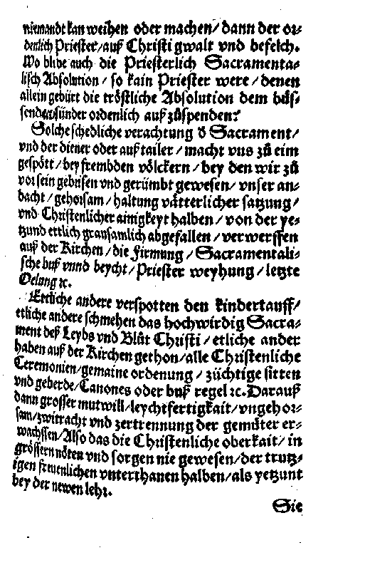
This example is taken from prog/dewarptest.c, and the
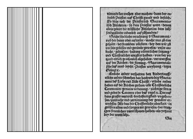
images were computed there. We start with image 1555-7.jpg.
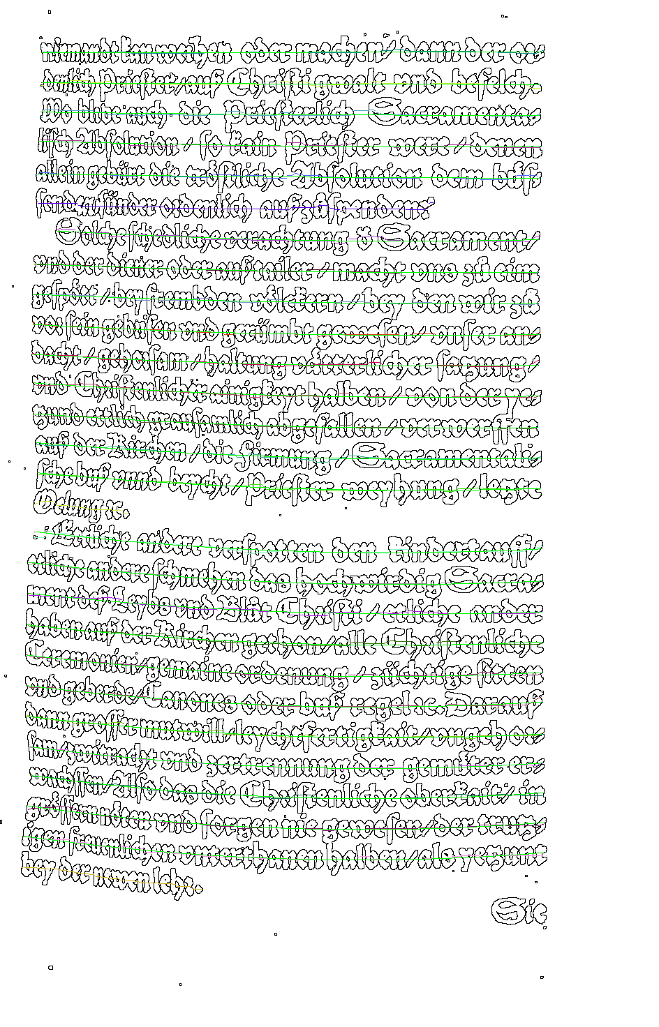
After doing background normalization and binarization, we get
this image:
We then find the centers of the textlines and do a least squares quadratic fit to the longest of them:
The contours of constant vertical disparity, calculated from these smoothed lines, and the dewarped result on the input image after applying the vertical disparity, are:
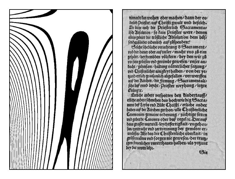
The horizontal disparity field is then applied to this image. The field and the final result are:
For this page the results look fairly ragged, but the baseline wobblyness
is in the original, which was typeset in a very crude manner. There are
still problems with the horizontal disparity because of our assumption
of y-independence. In any event, I believe that we do not have the
information available in the image to compute the horizontal disparity
with much higher accuracy. This is a challenge to the reader: if you
can figure out a way to find the horizontal disparity more accurately,
let me know (and for extra credit send me the result).
